Quartz Crystal
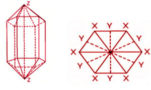
A natural crystal of quartz has a hexagonal prism structure, as illustrated in Fig 1.
The asymmetrical properties of quartz can be referred to three sets of major axes in the crystal. Z-axis runs along the length of the crystal and is called optical axis.
No doubt optical refraction occurs along this axis. The physical properties repeat themselves after every 1200 rotation about Z-axis.
The X-axis or the electric axis is parallel to a line bisecting the angles between adjacent prism faces. Electric polarization occurs along this direction when the mechanical pressure is applied.
The Y-axis, which is also known as the mechanical axis, is at right angles to the face of prism and also to the X-axis.
Fig.1 Quartz crystal structure Fig.2 Cross section of crystal perpendicular to axis ZZ
Crystal Cuts
The crystals used in crystal units are normally in the form of plates or elements cut from synthetic crystal(Fig. 3).

Fig.3 Cutting angles
Frequency Tolerance
The setting tolerance is the maximum allowable deviation from nominal frequency at a specified temperature typically 25°C. It is normally specified in parts per million (ppm) or percentage of nominal frequency.
Frequency – Temperature Characteristics
Fig.4 shows the
frequency-temperature characteristics for a thickness-shear mode At-Cut with the angle of cut as a parameter. Since the AT-cut frequency-temperature
characteristic is equivalent to an equation of the third degree, it displays excellent frequency stability over a wide temperature range.
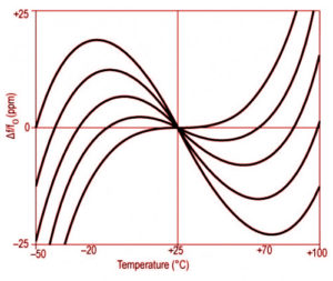
Fig.4 AT-cut frequency-temperature characteristics
Equivalent Circuit
The circuit, as show in Fig.5 denotes the quantities L1, C1, R1 and Co as the electrical equivalent of the electromechanical and electrical properties of the quartz and holder assembly. L1 and C1 are referred to as the motional inductance and capacitance respectively, and R1 is known as the effective series resistance (ESR).
Co is the static or shunt capacitance whose value is the sum of the capacitance between the electrodes and capacitances added by the leads and holder.
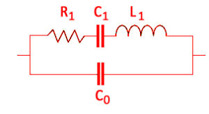
Fig.5 Equivalent Circuit
Equivalent Series Resistances (ESR)
The resistive element, measured in ohms, of a crystal device. At the frequency denoted by the following formula, the motional inductance (L) and motional capacitance (G) are of equal ohmic value are exactly opposite in phase, the net result is that they cancel one another and only a resistance remains in the series leg of the above equivalent circuit (Fig.5), The ESR measurement is made only at the series resonant frequency {Fs), not at some predetermined parallel resonant frequency (FL).
Crystal resistance measured at some paralled load resonant frequency is often called the effective resistance.

Motional Inductance (L1)
The inductance in the motional (series) arm of the equivalent circuit.
Motional Capacitance (C1)
The capacitance of the motional (series) arm of the equivalent circuit.
Shunt Capacitance (C0)
The static capacitance is the sum of electrode capacitance and holder capacitance
Overtone Crystals
Because of be physical properties and geometry of an AT cut quart blank, a crystal can vibrate at many frequencies.
The lowest frequency is called the fundamental frequency and can be supplied up to about 45 Hz Higher frequencies (to over 200MHz) are achieved by operating the crystal at odd
overtones, 3rd and 5th, and tuning the circuit so that the crystal oscillates at its designed overtone frequency (Fig.6).
Overtone crystals are specially processed for plane parallelism and surface finish in order to enhance their performance at the required overtone frequency. The overtone frequency is higher than the equivalent harmonic multiple o the fundamental by approximately 25MHz per overtone.
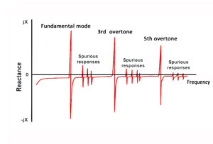
Fig.6 Overtone Response of a Quartz Crystal
Insulation Resistance
Resistance between crystal's leads, or between lead and case. It's standard values is 500M Ω min //DC100V.
Aging
Quartz crystal aging applies to the cumulative change in frequency which results in a permanent change in operating frequency of the crystal unit. The rate of change of frequency is fastest during the first forty-five days of operation.
Many interrelated factors are involved in aging, some of the most common being internal contamination, excessive drive level, surface change of the crystal. various thermal effects, wire fatigue and frictional wear. Proper circuit design incorporating low operating ambient, minimum drive level, and static pre-aging will greatly reduce all but the most severe aging problems.
Negative Resistance (-R)
The negative resistance (-R) is very important parameter to consider in an oscillator circuit.
The negative resistance (|-R|) must be sufficient to compensate for the resistance of the crystal and thus maintain a stable oscillation at a constant frequency.
The use of a circuit with an insufficient negative resistance may lead to such an unexpected trouble as the quartz crystal unit failing to initiate oscillation even when power has been switched on (Fig.8).
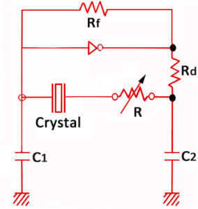
Fig. 8 Negative resistance
The oscillation circuit must be designed in such a way that the value of the negative resistance is 5 to 10 times larger than the equivalent series resistance of the quartz crystal unit. If the negative resistance (-R) is too low, it can make the crystal unstable.
¤ Checking the allowance for oscillation:
Add the resistance R to the circuit in series with the quartz crystal, adjust gradually R so that oscillation can start or stop and measure R when oscillation just starts or stops.
The approximate negative resistance of the circuit is obtained by adding R the equivalent resistance of the quartz crystal unit to the variable resistor R.
-R = R+R1
Spurious Response
It is also possible for a crystal to vibrate at a frequency that is not related to its fundamental or overtone frequencies. Such undesired frequencies are referred to as spurious responses (Fig.6).
The manufacturing processes are designed to minimize (not eliminate) the spurious responses and maximize the crystal activity at the desired frequency.
Drive level
Crystal drive level is the amount of power dissipated in a crystal which is usually specified in microwatts or milliwatts. the amplitude of mechanical vibrations of a quartz resonator increases proportionally to the amplitude of the applied power /voltage across it or the current through it.
As the drivel level increases the frequency and resistance of the crystal resonator change through non -linear effects. Drive level should be operated at the minimum level to avoid long-term frequency drift and crystal fracture.
Pullability
The pullability of a crystal refers to a crystal operating in the parallel mode and is a measure of the frequency change as a function of load capacitance. Pullability is important to the circuit designer who wishes to achieve several operating frequencies with a single crystal by means of switching various values of load capacitance.
Quality Form
“Q” of a crystal unit is the Quality Factor or the motional arm resonance. The higher the Q, the higher the frequency stability and accuracy capability of a resonator.
The maximum Q of a resonator can be expressed as:

where f is the frequency in Hz, and τ is an empirically determined “motional time constant” in seconds, which varies with the angles of cut and the mode of vibration.
Other factors which affect the Q of a resonator include :
Overtone, blank geometry, surface finish, material impurities and defects, drive level, mounting stresses, gases inside the enclosure, bonding stresses, temperature, interfering modes, electrode geometry and type , ionizing radiation.
A natural crystal of quartz has a hexagonal prism structure, as illustrated in Fig 1.
The asymmetrical properties of quartz can be referred to three sets of major axes in the crystal. Z-axis runs along the length of the crystal and is called optical axis.
No doubt optical refraction occurs along this axis. The physical properties repeat themselves after every 1200 rotation about Z-axis.
The X-axis or the electric axis is parallel to a line bisecting the angles between adjacent prism faces. Electric polarization occurs along this direction when the mechanical pressure is applied.
The Y-axis, which is also known as the mechanical axis, is at right angles to the face of prism and also to the X-axis.
Fig.1 Quartz crystal structure Fig.2 Cross section of crystal perpendicular to axis ZZ
The crystals used in crystal units are normally in the form of plates or elements cut from synthetic crystal(Fig. 3).
Fig.3 Cutting angles
The setting tolerance is the maximum allowable deviation from nominal frequency at a specified temperature typically 25°C. It is normally specified in parts per million (ppm) or percentage of nominal frequency.
Fig.4 shows the
frequency-temperature characteristics for a thickness-shear mode At-Cut with the angle of cut as a parameter. Since the AT-cut frequency-temperature
characteristic is equivalent to an equation of the third degree, it displays excellent frequency stability over a wide temperature range.
Fig.4 AT-cut frequency-temperature characteristics
The circuit, as show in Fig.5 denotes the quantities L1, C1, R1 and Co as the electrical equivalent of the electromechanical and electrical properties of the quartz and holder assembly. L1 and C1 are referred to as the motional inductance and capacitance respectively, and R1 is known as the effective series resistance (ESR).
Co is the static or shunt capacitance whose value is the sum of the capacitance between the electrodes and capacitances added by the leads and holder.
Fig.5 Equivalent Circuit
The resistive element, measured in ohms, of a crystal device. At the frequency denoted by the following formula, the motional inductance (L) and motional capacitance (G) are of equal ohmic value are exactly opposite in phase, the net result is that they cancel one another and only a resistance remains in the series leg of the above equivalent circuit (Fig.5), The ESR measurement is made only at the series resonant frequency {Fs), not at some predetermined parallel resonant frequency (FL).
Crystal resistance measured at some paralled load resonant frequency is often called the effective resistance.
The inductance in the motional (series) arm of the equivalent circuit.
The capacitance of the motional (series) arm of the equivalent circuit.
The static capacitance is the sum of electrode capacitance and holder capacitance
Because of be physical properties and geometry of an AT cut quart blank, a crystal can vibrate at many frequencies.
The lowest frequency is called the fundamental frequency and can be supplied up to about 45 Hz Higher frequencies (to over 200MHz) are achieved by operating the crystal at odd
overtones, 3rd and 5th, and tuning the circuit so that the crystal oscillates at its designed overtone frequency (Fig.6).
Overtone crystals are specially processed for plane parallelism and surface finish in order to enhance their performance at the required overtone frequency. The overtone frequency is higher than the equivalent harmonic multiple o the fundamental by approximately 25MHz per overtone.
Fig.6 Overtone Response of a Quartz Crystal
Resistance between crystal's leads, or between lead and case. It's standard values is 500M Ω min //DC100V.
Quartz crystal aging applies to the cumulative change in frequency which results in a permanent change in operating frequency of the crystal unit. The rate of change of frequency is fastest during the first forty-five days of operation.
Many interrelated factors are involved in aging, some of the most common being internal contamination, excessive drive level, surface change of the crystal. various thermal effects, wire fatigue and frictional wear. Proper circuit design incorporating low operating ambient, minimum drive level, and static pre-aging will greatly reduce all but the most severe aging problems.
The negative resistance (-R) is very important parameter to consider in an oscillator circuit.
The negative resistance (|-R|) must be sufficient to compensate for the resistance of the crystal and thus maintain a stable oscillation at a constant frequency.
The use of a circuit with an insufficient negative resistance may lead to such an unexpected trouble as the quartz crystal unit failing to initiate oscillation even when power has been switched on (Fig.8).
Fig. 8 Negative resistance
The oscillation circuit must be designed in such a way that the value of the negative resistance is 5 to 10 times larger than the equivalent series resistance of the quartz crystal unit. If the negative resistance (-R) is too low, it can make the crystal unstable.
¤ Checking the allowance for oscillation:
Add the resistance R to the circuit in series with the quartz crystal, adjust gradually R so that oscillation can start or stop and measure R when oscillation just starts or stops.
The approximate negative resistance of the circuit is obtained by adding R the equivalent resistance of the quartz crystal unit to the variable resistor R.
-R = R+R1
It is also possible for a crystal to vibrate at a frequency that is not related to its fundamental or overtone frequencies. Such undesired frequencies are referred to as spurious responses (Fig.6).
The manufacturing processes are designed to minimize (not eliminate) the spurious responses and maximize the crystal activity at the desired frequency.
Crystal drive level is the amount of power dissipated in a crystal which is usually specified in microwatts or milliwatts. the amplitude of mechanical vibrations of a quartz resonator increases proportionally to the amplitude of the applied power /voltage across it or the current through it.
As the drivel level increases the frequency and resistance of the crystal resonator change through non -linear effects. Drive level should be operated at the minimum level to avoid long-term frequency drift and crystal fracture.
The pullability of a crystal refers to a crystal operating in the parallel mode and is a measure of the frequency change as a function of load capacitance. Pullability is important to the circuit designer who wishes to achieve several operating frequencies with a single crystal by means of switching various values of load capacitance.
“Q” of a crystal unit is the Quality Factor or the motional arm resonance. The higher the Q, the higher the frequency stability and accuracy capability of a resonator.
The maximum Q of a resonator can be expressed as:
where f is the frequency in Hz, and τ is an empirically determined “motional time constant” in seconds, which varies with the angles of cut and the mode of vibration.
Other factors which affect the Q of a resonator include :
Overtone, blank geometry, surface finish, material impurities and defects, drive level, mounting stresses, gases inside the enclosure, bonding stresses, temperature, interfering modes, electrode geometry and type , ionizing radiation.